Shift Registers

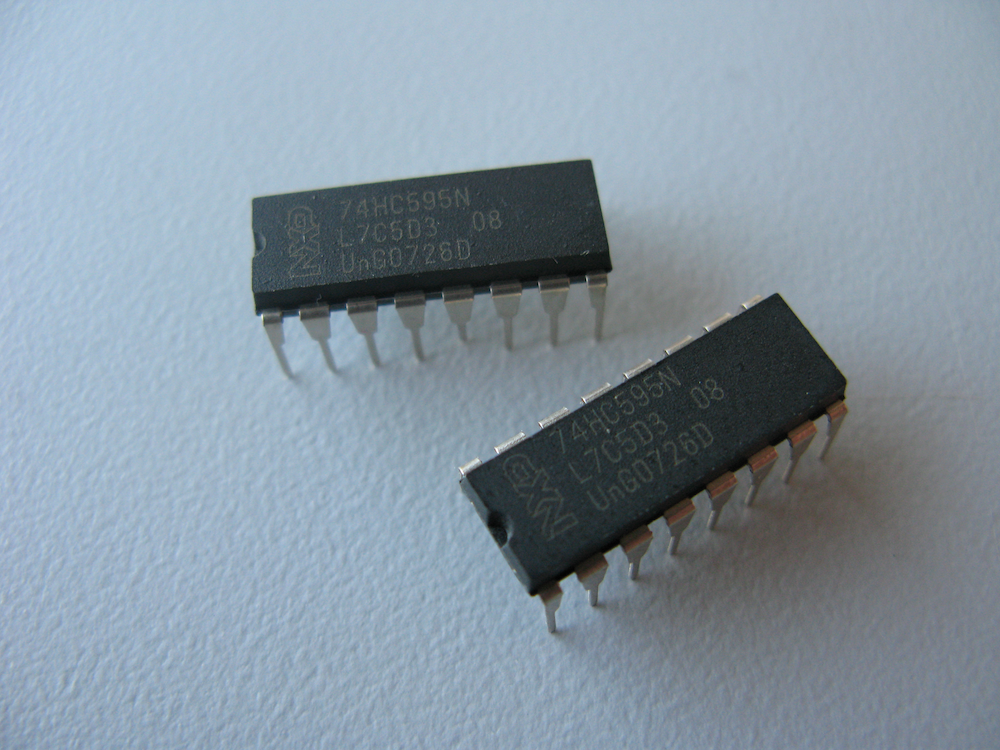
Shift Register: 74HC595N

Shift Registers are integrated components (IC) which allow one to control multiple inputs and outputs from a microcontroller i.e. Arduino. There are two basic types of Shift Registers – serial in to parallel out, and parallel in to serial out. In the first scenario, serial in to parallel out, controls multiple outputs, and parallel in to serial out controls multiple inputs. Shift Registers are used to manage digital input and output.

In the example below, we setup the 74HC595 – which is described as an 8-bit serial-in/serial or parallel-out shift register with output latches. The Shift Register can control 8 discrete outputs, through the use of 3 – 5 I/O pins on the your microcontroller. If you would like to control more than 8 discrete outputs, Shift Registers can be cascaded, or one could source a Shift Register with a larger bit count.

74HC595N & Arduino
74HC595N & Arduino

To setup the Shift Register for operation, connect the following pins from the Shift Register to your microcontroller and breadboard:


/*
Shift Register Wiring Schematic
 Q1 -|    |- VCC
 Q2 -|    |- Q0
 Q3 -|    |- DS
 Q4 -|    |- OE
 Q5 -|    |- ST_CP
 Q6 -|    |- SH_CP
 Q7 -|    |- MR
VSS -|    |- Q' 

Key:
Q0 - Q7: Parallel Out Pins
Q': Cascade Pin
DS: Serial Data In Pin
OE: Output Enable (Active Low)
ST_CP: Latch Pin
SH_CP: Clock Pin
MR: Master Reset  (Active Low)
*/

// ST_CP of 74HC595
#define LATCH_PIN 3;
// SH_CP of 74HC595
#define CLOCK_PIN 4;
// DS of 74HC595
#define DATA_PIN 2;

// Hex Character from 0 - F
byte hexArray[16] = 
{ 
  B11000000,  // 0 = { 1, 2, 3, 4, 5, 6 } 
  B11111001,  // 1 = { 2, 3 }
  B10100100,  // 2 = { 1, 2, 4, 5, 7} 
  B10110000,  // 3 = { 1, 2, 3, 4, 7}
  B10011001,  // 4 = { 2, 3, 6, 7}
  B10010010,  // 5 = { 1, 3, 4, 6, 7}
  B10000010,  // 6 = { 1, 3, 4, 5, 6, 7}
  B11111000,  // 7 = { 1, 2, 3}
  B10000000,  // 8 = { 1, 2, 3, 4, 5, 6, 7}
  B10010000,  // 9 = { 1, 2, 3, 4, 6, 7}
  B10001000,  // A = { 1, 2, 3, 5, 6, 7}
  B10000000,  // B = { 1, 2, 3, 4, 5, 6, 7}
  B11000110,  // C = { 1, 4, 5, 6}
  B11000000,  // D = { 1, 2, 3, 4, 5, 6}
  B10000110,  // E = { 1, 4, 5, 6, 7}
  B10001110,  // F = { 1, 5, 6, 7} 
};

void setup() 
{
  Serial.begin(9600);
  pinMode(LATCH_PIN, OUTPUT);
  pinMode(CLOCK_PIN, OUTPUT);
  pinMode(DATA_PIN, OUTPUT);
}

void sendToShiftRegister(int pot)
{
    digitalWrite(LATCH_PIN, LOW);
    shiftOut(DATA_PIN, CLOCK_PIN, MSBFIRST, hexArray[pot]);   
    digitalWrite(LATCH_PIN, HIGH);
    delay(20);
}

int getAnalog()
{
  int getAnalog = analogRead(0)/64;
  //Serial.println(getAnalog);
  return getAnalog;
}

void loop() 
{
  sendToShiftRegister(getAnalog());
  delay(25);
}