With around 1 billion chip produced every year, the 555 timer is the most produced chip around the world. Simply put, the 555 is an electrical timer, it can output current at a specified frequency, it work in two different modes : astable and monostable. Astable will continuously output current at a specified interval while monostable will output current for a fixed amount of time when the chip is triggered.
Usage
The 555 timer’s functionality may not seem so astonishing at first but since it was released in 1972, the 555 became the most successful chip ever produced, both by the number of units produced and by the robustness of its design. In fact, the 555 timer barely changed since it’s original creation. Why is a simple timer so useful? Think of it as the simplest way of controlling the duration of an electrical event.
For example, if you would be to make a toaster, how would you make sure the toasts stay in for exactly the period of time you want and come out? A 555 timer in monostable mode could effectively do that. Even better, if you want to make a toaster with an adjustable cooking time, you could simply add a variating resistor (such as a potentiometer for example) to let the user decide how long he wants the toast to cook.
A 555 timer in astable mode could be used, for example, to control a car’s wipers and have them move at a precise interval. In fact, it has been used for that function in the past.
One of the 555 timer’s most impressive feature is it’s ability to be chained with other 555 timers to create various effect. Imagine, for instance, that you want to have a robot that makes a sound for a certain amount of time, then flashes it’s eyes quickly for an other amount of time. In order to do that, you could have a first 555 timer in monostable mode (triggered by a button on the robot or anything else) used to control the time that you output current to the speaker to make the robot scream. Once this delay is over, the first 555 timer could output voltage to the trigger of a second 555. 555 #2 would power up, for a specified amount of time, a third 555 in astable mode that would make the eyes blink at a specific interval.
In other words, 555 timers can be chained to create precise sequence of events over time. Figure 2 shows example of chained 555 timer.
chained 555 timers
Source : Charles Platt, Make:Electronics
Inside the plastic body
The standard 555 package includes 25 transistors, 2 diodes and 15 resistors on a silicon chip installed in an 8-pin mini dual-in-line package. It would be to complex to explain here the details of how it works but the interesting thing is that all these components end up making an easy interface that you can use to control durations and periods without any micro-controller or computational logic.
Pin description
Figure 1 shows what each pin do but here is a more detailed description.
Pin 1 (Ground):
Connects to the 0v power supply.
Pin 2 (Trigger):
Detects 1/3 of rail voltage to make output HIGH. Pin 2 has control over pin 6. If pin 2 is LOW, and pin 6 LOW, output goes and stays HIGH. If pin 6 HIGH, and pin 2 goes LOW, output goes LOW while pin 2 LOW. This pin has a very high impedance (about 10M) and will trigger with about 1uA.
Pin 3 (Output):
(Pins 3 and 7 are “in phase.”) Goes HIGH (about 2v less than rail) and LOW (about 0.5v less than 0v) and will deliver up to 200mA.
Pin 4 (Reset):
Internally connected HIGH via 100k. Must be taken below 0.8v to reset the chip.
Pin 5 (Control):
A voltage applied to this pin will vary the timing of the RC network (quite considerably).
Pin 6 (Threshold):
Detects 2/3 of rail voltage to make output LOW only if pin 2 is HIGH. This pin has a very high impedance (about 10M) and will trigger with about 0.2uA.
Pin 7 (Discharge):
Goes LOW when pin 6 detects 2/3 rail voltage but pin 2 must be HIGH. If pin 2 is HIGH, pin 6 can be HIGH or LOW and pin 7 remains LOW. Goes OPEN (HIGH) and stays HIGH when pin 2 detects 1/3 rail voltage (even as a LOW pulse) when pin 6 is LOW. (Pins 7 and 3 are “in phase.”) Pin 7 is equal to pin 3 but pin 7 does not go high – it goes OPEN. But it goes LOW and will sink about 200mA.
Pin 8 (Supply):
Connects to the positive power supply (Vs). This can be any voltage between 4.5V and 15V DC, but is commonly 5V DC when working with digital ICs.
How to hook it up
This example is taken from Peter Flemming’s amazing IMCA222 notes (http://hybrid.concordia.ca/pflemmin/IMCA222.html#555) and shows you how to simply connect a 555 in astable mode :
555 howto
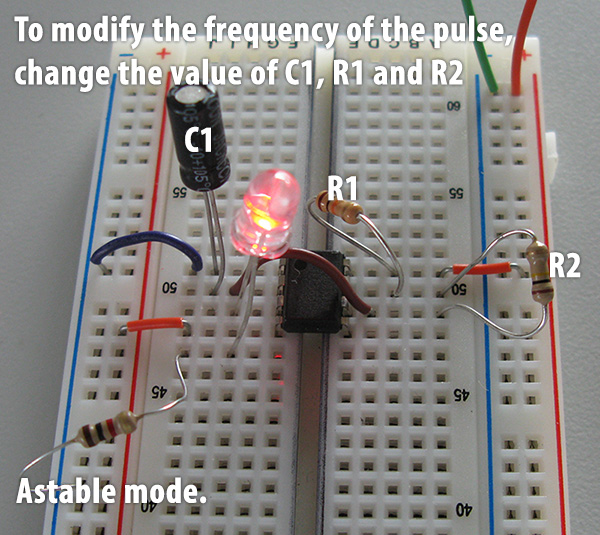
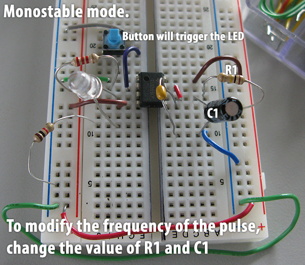
We also wired a 555 both in monostable mode and astable mode to show you how to do it:
The astable mode will continuously emit it’s pulse. For example, by putting the 555 timer with an LED, you would make the LED blink continuously. This image shows how you would use a 555 timer, in astable mode, to light an LED :
Astable Mode
The monostable mode will wait for a trigger before sending voltage (trigger is on pin 2). Once it is triggered, it will send current for the specified delay, then shut off.
Monostable ModePulse duration
For the monostable mode, the following diagram explains how resistor and capacitor will affect the pulse duration (click to enlarge) :
Pulse Chart
Source : Charles Platt, Make:Electronics
Online documentation and ressources:
http://freespace.virgin.net/matt.waite/resource/handy/pinouts/555/ : an excellent source to find out how to hook up the 555 timer in both monostable and astable mode. It also has an online tool to find out what will be the delay between each pulse depending on which capacitor and resistors you use.